VLSI Lab 4 Verilog MegaWizard IP Generator and Chip Planner (Compiled on Quartus II v20.1)
VLSI Lab 4, EIE
Laboratory Objectives
The objectives of this laboratory are:
·
Understand the use of
Altera’s MegaWizard IP generator: (https://ftp.intel.com/Public/Pub/fpgaup/pub/Teaching_Materials/current/Tutorials/Verilog/Using_Library_Modules.pdf)
·
How to
specify synthesis options
and their impact
·
Understand the impact
of placement on the design
quality using Pin Planner
Top entry sqrt.v file:
// ----- EIE Lab 4// ----- https://vlsiorfpgadesign.blogspot.com/ ----- //
// Using IP core ALTSQRT
module sqrt (
sqrt_in,
sqrt_out);
parameter width = 4; // # bits
input [width-1:0] sqrt_in;
output [width:0] sqrt_out;
wire [width/2-1:0] q_sig; // quotient
wire [width/2:0] remainder_sig; // rmainder
sqrt_ip U1_sqrt_inst (
.radical(sqrt_in),
.q(q_sig),
.remainder(remainder_sig));
assign sqrt_out = {q_sig[width/2-1:0], remainder_sig[width/2:0]};
endmodule
// -------------------------------------- //
Testbench file: sqrt_tb.v
// ***** https://vlsiorfpgadesign.blogspot.com *****
// Generated on "03/15/2022 17:35:48"
// Verilog Test Bench template for design : sqrt
// Simulation tool : ModelSim-Altera (Verilog)
`timescale 1 ps/ 1 ps
module sqrt_vlg_tst();
// constants
// general purpose registers
reg eachvec;
// test vector input registers
reg [3:0] sqrt_in;
// wires
wire [4:0] sqrt_out;
// duration for each bit = 1 * timescale = 1 * 1 ns = 1ns
localparam period = 1;
// assign statements (if any)
sqrt i1 (
// port map - connection between master ports and signals/registers
.sqrt_in(sqrt_in),
.sqrt_out(sqrt_out)
);
initial
begin
// code that executes only once
$display("Running testbench");
end
// optional sensitivity list
// @(event1 or event2 or .... eventn)
initial begin
// code executes for every event on sensitivity list
// insert code here --> begin
//@eachvec;
sqrt_in = 0;
#period;
sqrt_in = 'h2;
#period;
sqrt_in = 'h4;
#period;
sqrt_in = 'h9;
#period;
sqrt_in = 2;
#period;
sqrt_in = 4;
#period;
sqrt_in = 9;
#period;
// --> end
end
endmodule
// ------------------------------ //
Below is another version that is added with flip-flops so as to check the Fmax of the SQRT:
Google drive: https://drive.google.com/file/d/1NHtUlqEI5-n91SNyGO_oP-cUZMEraoAj/view?usp=sharing
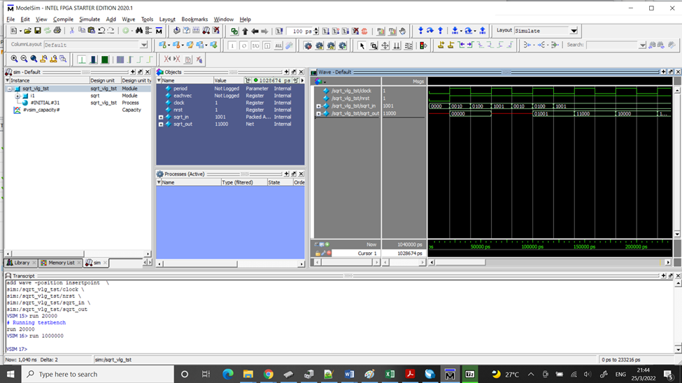
(Click to enlarge) (with clock added to the test bench)

// ------------------------------------------------------------------------ //
// -------------- * Optional Another Reference Design * --------- //
<< Square-Rooter with 5 bits >>
Below is another test design of square rooter with the width of 5 bits:
File: sqrt_ip.v
module sqrt_ip (
radical,
q,
remainder);
input [4:0] radical;
output [2:0] q;
output [3:0] remainder;
wire [2:0] sub_wire0;
wire [3:0] sub_wire1;
wire [2:0] q = sub_wire0[2:0];
wire [3:0] remainder = sub_wire1[3:0];
altsqrt ALTSQRT_component (
.radical (radical),
.q (sub_wire0),
.remainder (sub_wire1)
// synopsys translate_off
,
.aclr (),
.clk (),
.ena ()
// synopsys translate_on
);
defparam
ALTSQRT_component.pipeline = 0,
ALTSQRT_component.q_port_width = 3,
ALTSQRT_component.r_port_width = 4,
ALTSQRT_component.width = 5;endmodule
-------
Top-entry design file: sqrt.v
// Using IP core ALTSQRT (longer width 5 bits)module sqrt (sqrt_in,sqrt_out);parameter width = 5; // # bitsinput [width-1:0] sqrt_in;output [width+1:0] sqrt_out;wire [width-2-1:0] q_sig; // quotientwire [width-2:0] remainder_sig; // rmaindersqrt_ip U1_sqrt_inst (.radical(sqrt_in),.q(q_sig),.remainder(remainder_sig));assign sqrt_out = {q_sig[width-2-1:0], remainder_sig[width-2:0]};endmodule
Testbench file: sqrt_tb.v (for longer width of 5 bits input)
// ***** https://vlsiorfpgadesign.blogspot.com *****
// Simulation tool : ModelSim-Altera (Verilog)
`timescale 1 ps/ 1 psmodule sqrt_vlg_tst();reg eachvec;reg [4:0] sqrt_in;wire [6:0] sqrt_out;// duration for each bit = 1 * timescale = 1 * 1 ns = 1nslocalparam period = 2;sqrt i1 (// port map - connection between master ports and signals/registers.sqrt_in(sqrt_in),.sqrt_out(sqrt_out));initialbegin// code that executes only once$display("Running testbench");end// optional sensitivity list// @(event1 or event2 or .... eventn)initial begin// code executes for every event on sensitivity listsqrt_in = 0;#period;sqrt_in = 'h2;#period;sqrt_in = 'h4;#period;sqrt_in = 'h9;#period;sqrt_in = 25;#period;sqrt_in = 2;#period;sqrt_in = 9;#period;sqrt_in = 16;#period;sqrt_in = 4;#period;sqrt_in = 6;#period;sqrt_in = 7;#period;sqrt_in = 8;#period;sqrt_in = 9;#period;sqrt_in = 10;#period;sqrt_in = 12;#period;sqrt_in = 15;#period;sqrt_in = 25;#period;// --> endendendmodule
Modelsim Results (width 5 bits):
Simulate the test bench sqrt_vlg_tst under "work"


Note that you also need to compile the IP simulation libraries of the Altera / Intel FPGA in the installation folder, e.g.: C:\intelFPGA_lite\20.1\quartus\eda\sim_lib\altera_mf.v


留言
張貼留言